UNIVERSITY OF TORONTO ROBOTICS ASSOCIATION SUMO CLUB
SEPTEMBER 2017 - APRIL 2018


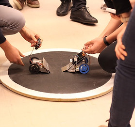
As part of a three-person team, I was in charge of designing and building the mechanical portion of a sumo robot. Like sumo wrestling in real life, the goal of the sumo robot is to push opponents out of a ring, and to avoid being pushed out. Our team’s robot had an effective design, as it won first place in the inter-university competition. Each of us maintained a similar sense of responsibility and workload, allowing us to complete the robot by the time constraint.
I designed the body of the robot based on the following specifications set by my team and I:
-
Meets size requirement for the competition (12 cm x 12 cm)
-
Low height for low center of gravity
-
Wheels at the back so that the front of the robot can rotate at its fastest rate in respect to a vertical axis (for higher mobility)
-
Ramp has a low incline to lift opponents with minimal energy, rather than a ramp with a high incline that would result in only pushing the opponent
-
Lightweight to allow for optimal mobility (trade off is that a lighter robot is easier to push)
-
Forked ramp to ‘capture’ opponents (making escape more difficult)
-
Space for motors and circuitry
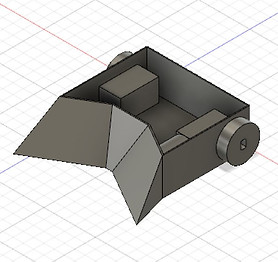


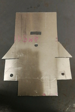
In order to design the robot's body, I used AutoCAD Fusion 360. The first image in the top left shows our initial design. However, the geometry was too complex to make by bending and cutting sheet metal (our club's method of construction), so our design was modified into the design shown in the second image, removing the forked ramp design. The third image shows that same design, but unfolded. This iteration of the design made use of AutoCAD Fusion 360's sheet metal tools.
An exported drawing was then used to provide measurements in order to construct the body. The cut sheet metal is shown in the image below, which was made using jigsaw, snips and a power drill. The body was then bent into shape using a bending brake. Holes were also added to account for the optical and line sensor.

After bending the sheet metal body, we realized that the ramp face did not reach the ground as intended, which would affect how well the ramp would function. To alleviate this, we glued a second, smaller panel of sheet metal on to the ramp.

Overall, I believe the success of the sumo robot is due to our teamwork and planning. Before beginning any design process, we listed requirements and goals for our robot.
Our teamwork allowed us to plan out the sumo robot well, as each of us were not only open to each other’s input, but we encouraged it. This allowed certain design aspects to be brought to light each of us may have overseen individually. Despite generally working on different aspects of the robot, each of the members considered interdisciplinary aspects.
After having competed, here are some final thoughts on how we could improve our design:
-
Because we did not have a proper mounting system, the optical sensor was positioned normal to the ramp's face. This meant that in order to sense an opponent, our robot would have to be closer compared to others (sensing at an upwards angle). A design to keep the sensor horizontal should be considered. For example, a portion of sheet metal from the hole could be bent backwards and act as a support.
-
A panel to protect the circuitry would be beneficial in the case of being knocked over, or during transportation of the robot. This was not done due to time constraints.