UNIVERSITY OF TORONTO ROBOTICS FOR SPACE EXPLORATION

As a member of the Robotics for Space Exploration, I design and build components for a Mars Rover that participates in international competitions, such as the University Rover Challenge, Canadian International Rover Challenge, and the European Rover Challenge. These competitions simulate Mars Missions, such as soil sample collection, astronaut search and rescue, and equipment servicing.
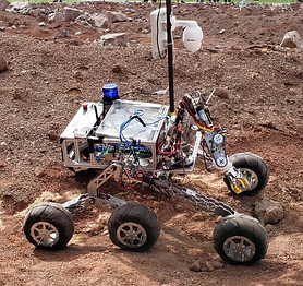
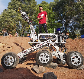
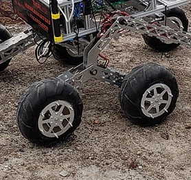
Our last season's rover, Rugged Phoenix, features an aluminium rocker-bogie suspension system, custom polyurethane tires, and a 6 DOF arm. A video showcasing this version of the rover is included below.
Robotics for Space Exploration consists of multidisciplinary sub teams who work on many different aspects in order to deliver the final product. For the 2019-2020 season, I've been selected for the leadership position as Mechanical Lead. This position requires excellent communication skills in order to organize and collaborate with team members, and to contact companies for services. Flexibility is another important asset to overcome any unexpected obstacles that our team may encounter.
SEPTEMBER 2019 - PRESENT
MECHANICAL SYSTEM


As the Mechanical Lead, I successfully guided the Mechanical Team to complete a SolidWorks model of our rover, and to complete its fabrication. I helped to draft design specifications for all the components, which I assigned to team members to model. During this process, I provided constant feedback and support based on my previous experience and knowledge of real-life fabrication of the parts. I also contributed to designing several parts, which were reiterated and improved on by myself and other members. I finalized the complete SolidWorks model that included all the member's contributions, which I was able to use to finalize part orders and technical drawings for vendors. During the fabrication phase, I machined several parts for the gearbox using a lathe and mill. I also guided my team members on tool safety as I helped them complete their parts.
CARBON FIBER ROCKER-BOGIE

To minimize the weight of previous rocker-bogie designs, this year I decided to include the use of carbon fiber tubing. Several design considerations include:
-
When attached to the chassis, the rover's overall dimensions must fit within 1.2m x 1.2m x 1.2m
-
Must be able to support 25kg (for each side, maximum rover weight is 50kg)
-
Economically feasible (within our team's budget)
The necessary cross-sectional profile for the tubes were determined using solid mechanic calculations. After selecting the correct size tubing from a vendor, the aluminium plating and tube lengths were modeled and adjusted visually based on SolidWorks Motion Analysis. Some other adjustments I made include:
-
Removing the carbon fiber tube from one of the linkages to increase mobility
-
Adding a 'bumper' to one of the brackets to avoid crushing the middle gearbox and carbon fiber in the rocker
-
Increasing clearance between the middle linkage and the carbon fiber tube
-
Location of the attachment to our differential system
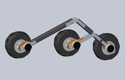
Throughout these adjustments, one of my team members and I analysed the rocker bogie through ANSYS to ensure it was structurally feasible. We were also able to determine our aluminium plating thickness through our analysis, based on the available aluminium alloys of our sponsoring vendors (6065 Aluminium Alloy).


We determined our rocker-bogie to have a safety factor of 30. After doing additional analyses (individual parts, applying a weight of 1000N rather than the required 500N, applying a horizontal force), I developed technical drawings which were sent out to the vendors to fabricate. The completed rocker-bogie is shown below.

CUSTOM GEARBOX


As our team decided to buy more reliable and efficient motors than previous years, a new solution for increasing the torque was required. After I completed calculations to determine our required gear ratio and battery voltage for the motors, our options included:
-
Buying compatible gearboxes off-the-shelf
-
Modifying gearboxes off-the-shelf
-
Building our own custom gearboxes with off-the-shelf gears
-
Building our own custom gearboxes with gears that we machine ourselves
The biggest constraint in our decision making was cost, as the new motors as well as carbon fiber for the rocker-bogie already put our budget much higher than previous years. We decided to build a custom gearbox using off-the-shelf gears, as this was cheaper than buying assembled gearboxes off-the-shelf, and more reliable than machining our own gears. After selecting our gears for our required gear ratio, we used solid mechanic calculations to determine the required shaft length and diameter in order to support our motor torque and rover's weight. The type of bearings were selected based primarily on their radial load rating as well as cost. I also opted for a 3-D Printed casing to protect the gears from dirt and dust. This casing also functions as a spacer, that prevents the two parallel aluminum plates from moving independently from each other.
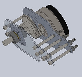
After making these design decisions, I modeled the gearbox in SolidWorks. Team members made several contributions as well, such as adding a plate to press fit the bearings in, and adding other components such as collar shaft clamps and bolts.
After receiving our gears, I machined several components in order to keep the spur gear constrained on the motor shaft, and adding a keyway on the large gear. The completed gearbox is shown below.


SEPTEMBER 2018 - AUGUST 2019
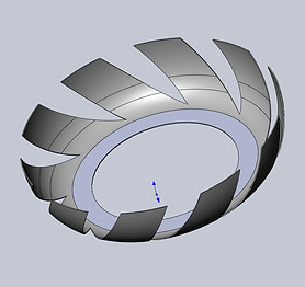
CUSTOM POLYURETHANE TIRES

For the 2018-2019 season, I've been tasked with redesigning our polyurethane tires, and the mold required to make them. The following considerations were made when redesigning the tire mold:
-
The tire diameter needed to increase to compensate for a larger rocker bogie size compared to last year's model
-
The method of holding the mold together using bolts from the last mold model was difficult to fasten when wearing gloves and dealing with polyurethane, as the molding process requires a slippery applicant
-
As such, the new mold design should have an ergonomic way to fasten the mold before the injection process, for example, using a hinge and clamps
-
-
If possible, add tire treads in order to improve the rover's traction
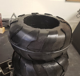
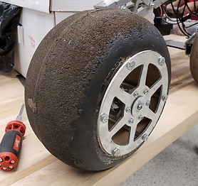
Our previous tire and tire mold are shown below:
Using SolidWorks, I modeled the tire and tire mold so we could visualize how to best address the biggest challenge; making the treads. Besides simply gluing on individual treads to the tires, our best design idea was to implement an inner track inside the mold, with sections cut out, which would form the treads when filled by the polyurethane. The final SolidWorks model of the entire mold assembly, and one of the inner tracks is shown below.
A few changes were made when the SolidWork drawings were sent to Kenspin LTD, a local metal spinning company who were willing to help make the mold. For example, the thickness of both the outer molds and the inner tracks were changed to 1mm based on their capabilities. Although this changes the thickness of the treads, and may consequentially change how effective the treads are, our team decided experimenting and prototyping treads would be a helpful step for the future.

Here are some of the ideas our team thought of in order to make the inner track:
-
Make the inner track out of foam, and use a foam cutter to create the cut out sections
-
The high temperatures when molding would not be an issue, as the core used for the old tires were still intact. Packing tape was used to prevent polyurethane from sticking to the mold. However, the foam cutter on our campus is similar to a band saw, so it would be very difficult to replicate the curved geometry. This could be compensated by creating the inner track through several smaller pieces, however this would be very time consuming and inconsistent (as everything would be hand cut).
-
-
3D Print the inner track
-
SLA 3D Printing is commonly used in industry for molds, and has very high resolution and accuracy for complex geometries. Unfortunately, after receiving some quotes, this method was too expensive for our budget.
-
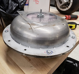
Luckily, the professionals at Kenspin LTD managed to find a much simpler solution than our team expected. They cut a pattern out on sheet metal, then hammered the sheet metal into the outer molds so that the sheet metal would take on its curved shape. The final mold parts are shown below:


Following the philosophy that sometimes the best solution is the simplest solution, we opted to change the nuts to fly nuts, rather than implementing hinges and a clamp.
Finally, we used the completed mold to manufacture our tire at Talmolder, one of our continuing sponsors. Polyurethane was injected into the mold, and after cooling, was removed. We removed the parting line and other unwanted details with an exacto knife. Below are some images of one of the polyurethane injection machines, as well as a video of the Mechanical Lead removing a tire from the mold.


After finishing the molding process of the tires and competing at the Canadian International Rover Challenge, here are some possible improvements for next year:
-
Because of the thinness of the mold, by the end of molding the tires, parts of the mold began to crack, especially at the seem where the flange begins. This is fine if we had a new mold made for every year. If we wanted to keep the same mold for the future, we could possibly weld at the seem.
-
There is no reason for the tires to be directional, as during competition (or a simulated Mars Mission), the rover travels in several directions. As such, the treads should be just as effective when the tires are back driven.
-
The large hole on the one half of the outer mold is unnecessary. Our team thought that this was needed for the molding process, but we ended up just covering it with acrylic.
-
There should be a better method for aligning the inner track. The polyurethane somewhat sticks, so they are removed each time a tire is made. Each time we restarted the molding process for a tire, we had to realign the tracks so that the treads were symmetrical by eye. Perhaps the inner tracks can be attached to the outer molds with tape or welding.
Also, due to a delay in other components of the rover, testing occurred later than expected, and comparisons between the new tires and old tires were not conducted. Before deciding upon a new design, the effectiveness of this iteration of the tire should be investigated.
SEPTEMBER 2017 - AUGUST 2018
ARM BASE BEARING CRADLE


I designed a cradle to hold the bottom bearing at the base of the robotic arm. A rod extends from the base to allow the arm to maintain a stable upright position, otherwise the weight would cause it to tip over. A thrust bearing at the top carries most of the weight, and the bottom bearing allows for smooth rotation. I used SolidWorks to design the cradle, which holds the bearing in place, and secures to the outer steel tube with screws. I added a groove so that the inner ring can rotate freely without friction. I later submitted a SolidWorks drawing of the part to the Arm Lead to be machined.
As can be seen by the final product on the right, the method of attaching the cradle was changed, as the steel tube would be difficult to accurately drill through. Instead, a large bolt runs through the bearing and attaches to the rod, securing the cradle in place.